


Depending on how you attacked this project, you may have begun the wiring as soon as you had the thing up on it's wheels...or with the 7A..on a cardboard box. Whatever the case, this is as good a time as any to get down to business on the planning and execution of all the stuff that makes this thing really fly. Riveting stuff together is great, especially when you have plans. By now you've probably noticed a severe lack of direction in the manual. You've been taken by the hand through many of the steps up to this point. Now it's up to you to maneuver through a myriad of details in system planning and setup. ALWAYS REMEMBER THAT YOU WILL NEED ACCESS TO THIS STUFF LATER. ALSO, REMEMBER THAT SOLID RIVETS ARE USED IN THAT UPPER SKIN..SO LEAVE YOURSELF ROOM FOR YOUR ARMS & HANDS. At no other time during the project will you have a better opportunity to assure adequate access is maintained. Take a little extra time thinking about what it's gonna look like and what may be covered up...and out of reach! You'll pat yourself on the back later..believe me. I'll give some good hints on ways to do this throughout this section.
![]()

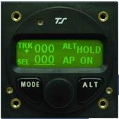
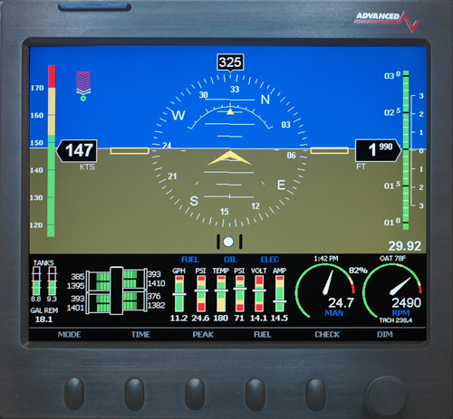
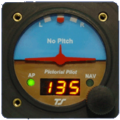
Images are linked to the manufacturers
Keep in mind, Van's does sell a basic wiring kit and directions to go with it. It's a pretty good deal and I highly recommend that you buy it. If anything it will give you the wiring for the basic stuff. The schematics (wiring diagram) will provide a head start on the system. You'll see how they drew it up, how the wires are made, what wires sizes were used for various components..etc..etc. I'ts good info.
The theory behind Van's plans remained the same in this project. I just added more stuff and developed my own schematics. .

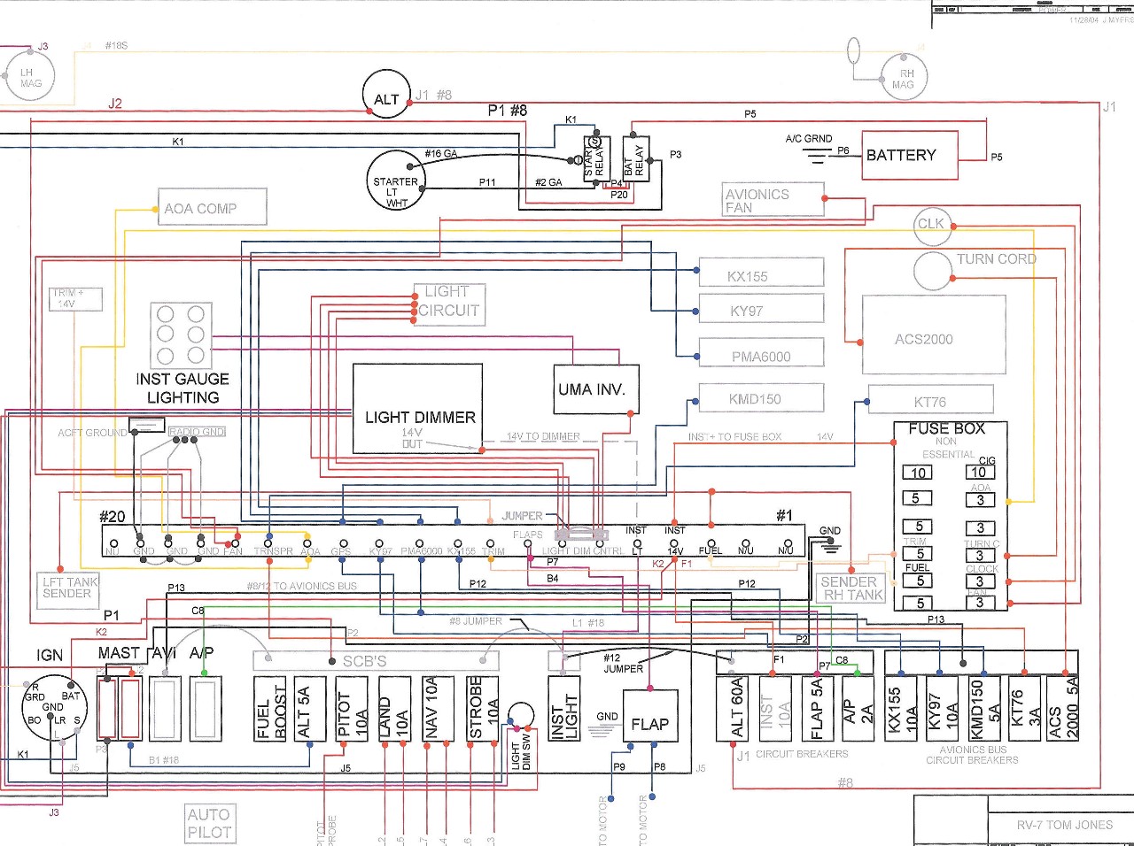
I don't know if you can read much but that's not the point. I wanted you to see this so that you realize that there's some planning to do. A napkin ain't gonna work for this bad boy. Take some time with a ruler and some paper. Lay it all out. CAD programs really work nice because you can zoom into different sections. It's really like you're in the thing. You can travel around from box to box. each place can be the size of your screen, giving you ample room to see the different lines. This in itself is really a key point. Drawing the stuff by hand can mix you up because all the lines blend in. Erasing just smears the stuff together. I used AutoCad Mechanical Desktop for this. If you don't have the luxury of Auto Cad, using a simple CAD program works well. You might find a free download that you can get it done with before the program goes dead. If none of this seems do-able go to Walmart and buy yourself some white poster paper and a ruler. Don't forget a few different colored pencils.
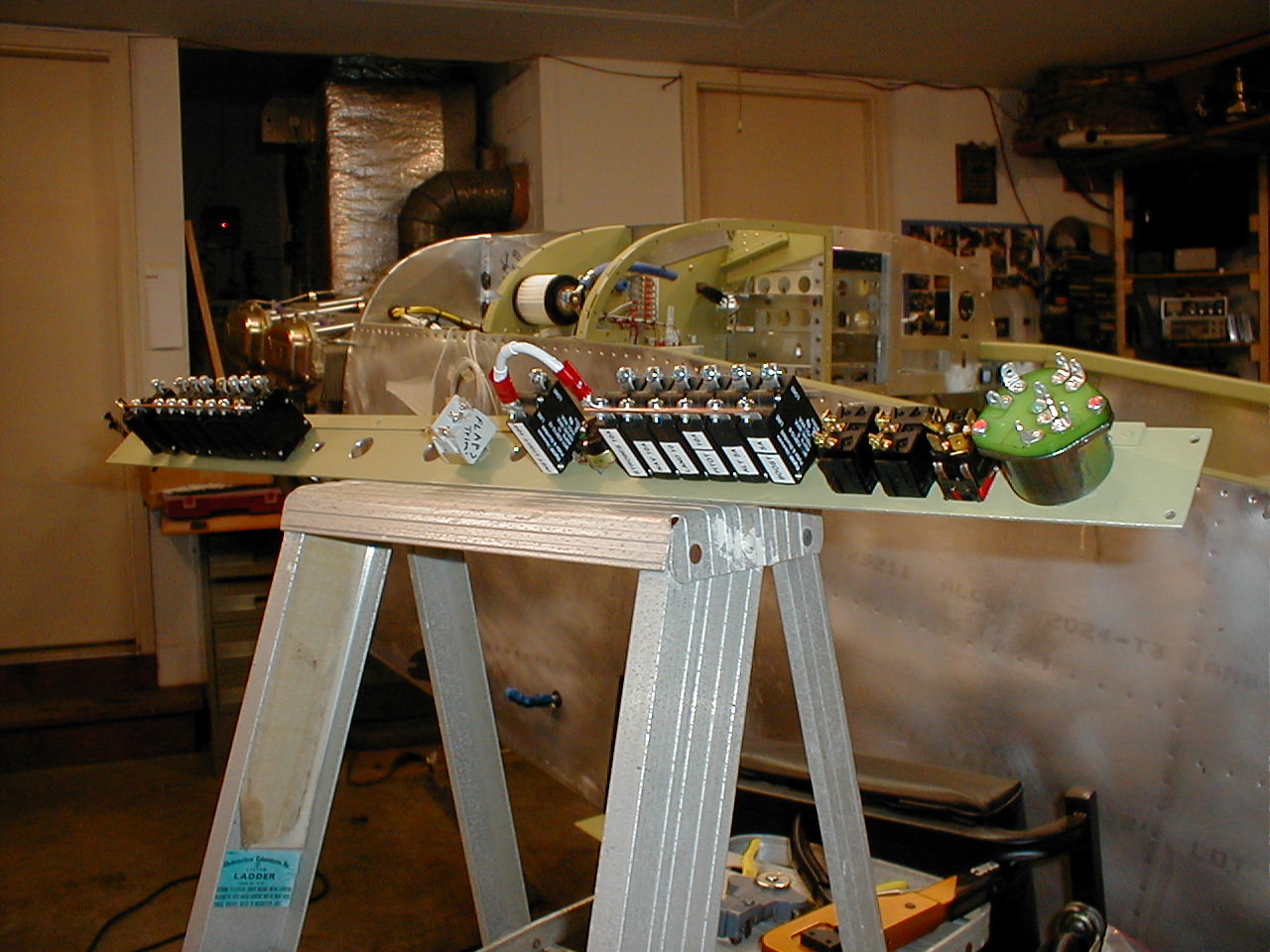
The layout above is a diagram of where the power is going. I have another done specifically for avionics and audio. The reason for this is simple. One is for power. The others are signal paths. The 'pin outs' from each unit are drawn on the single diagram. From there they enter the maze and end up connected. Instead of trying to trace this stuff with a stack of manuals in the plane, I've used a two page (taped together) layout showing all the stuff I needed to connect at each unit. All the headwork was done in the office at the computer. This beats standing on your head in a super heated garage while you try to figure it out. Believe me, I don't like eating my lunch twice. Being in that cockpit will bring tears to your eyes. Do as much as you can on the ole computer. It's a nice break anyway!
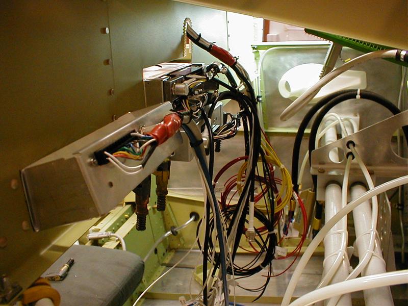
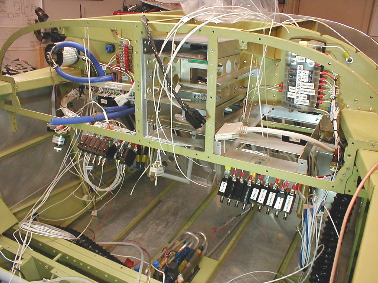
I almost forgot about the pictures. Here we go..
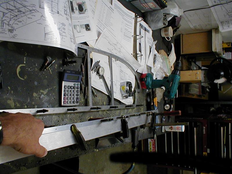
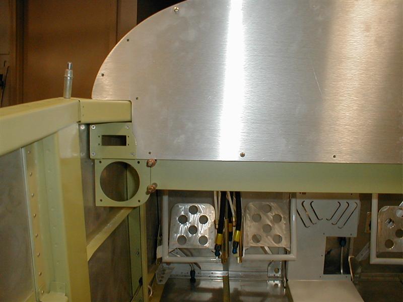
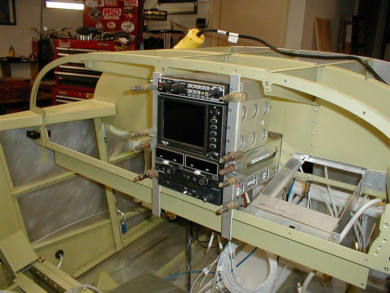
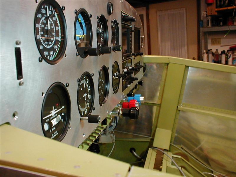
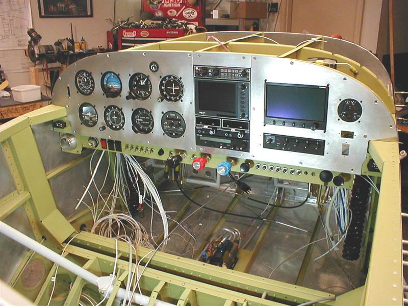
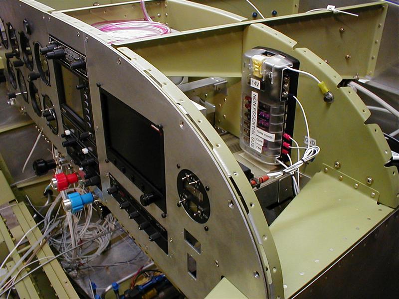
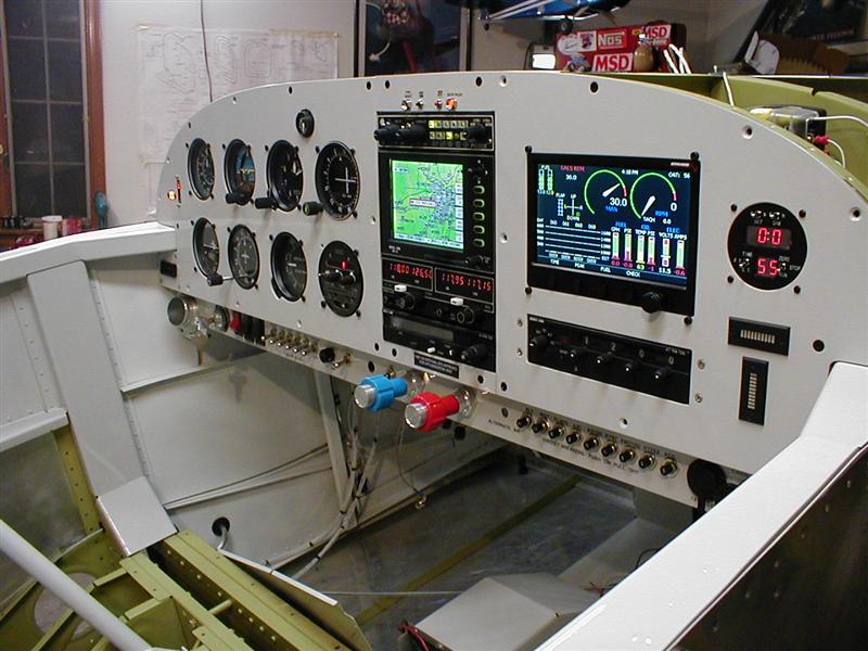
Yes, this is a shot of the Affordable Panels setup being figured out. I love the panel but the instructions were a little tuff. Most of it was self explanatory but the bottom section was a bit of a puzzle. Maybe I'm just spoiled with the CAD stuff. Anyway, it's only metal. If there's a 'wil' there's always a way. Be cognizant of the corner areas where the vent balls go. There is numerous ways to attach those ends. I'll leave the plans to the guys that designed it but don't be afraid to modify it. By now there's enough info out there. In the end, it's about the best thing going if you need the real estate for more gadgets. Here's the shortcut for instructions..http://www.affordablepanels.com/downloads.htm

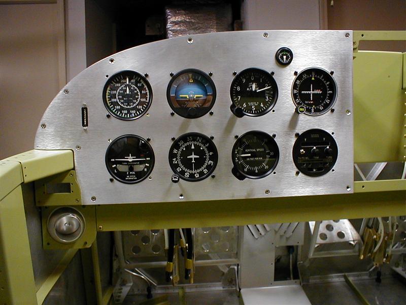
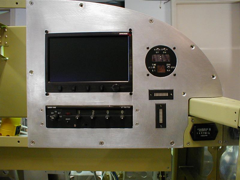
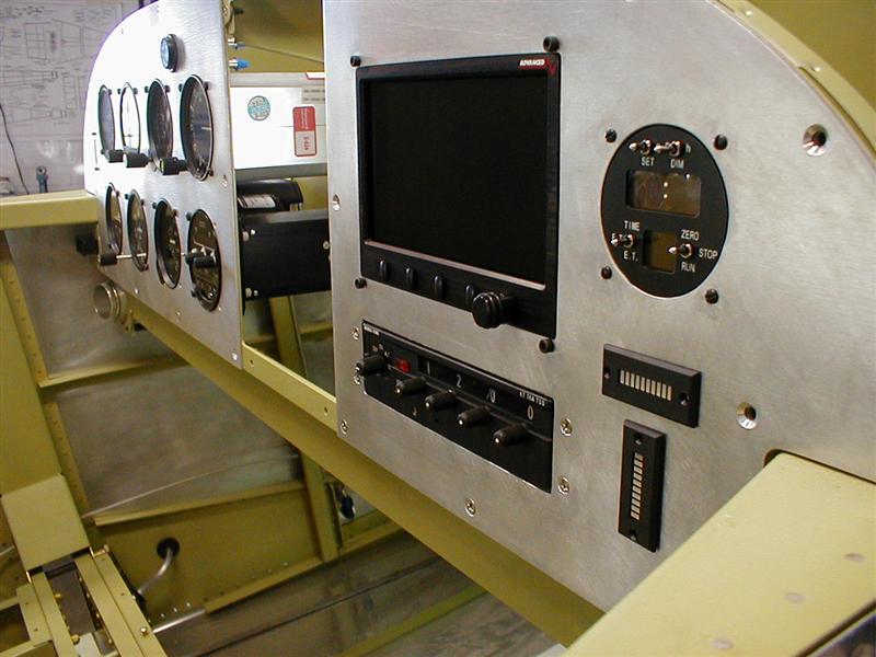
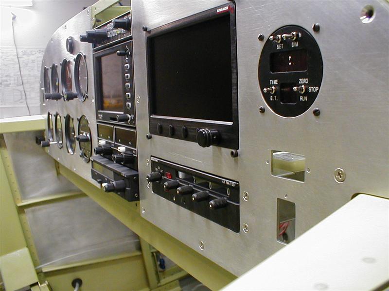
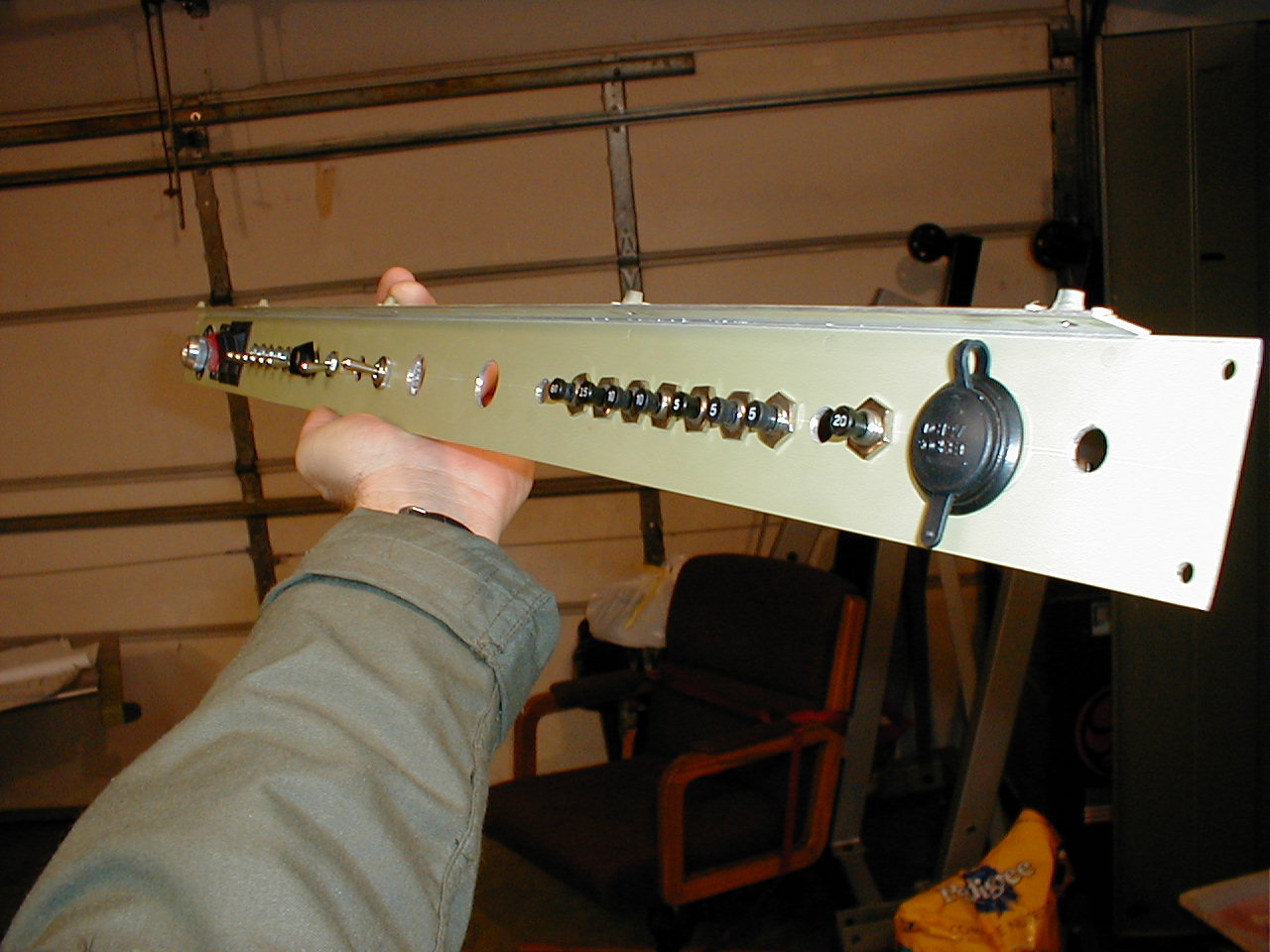
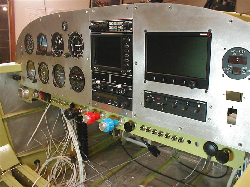
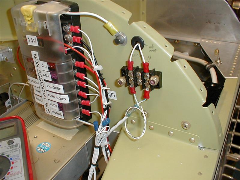
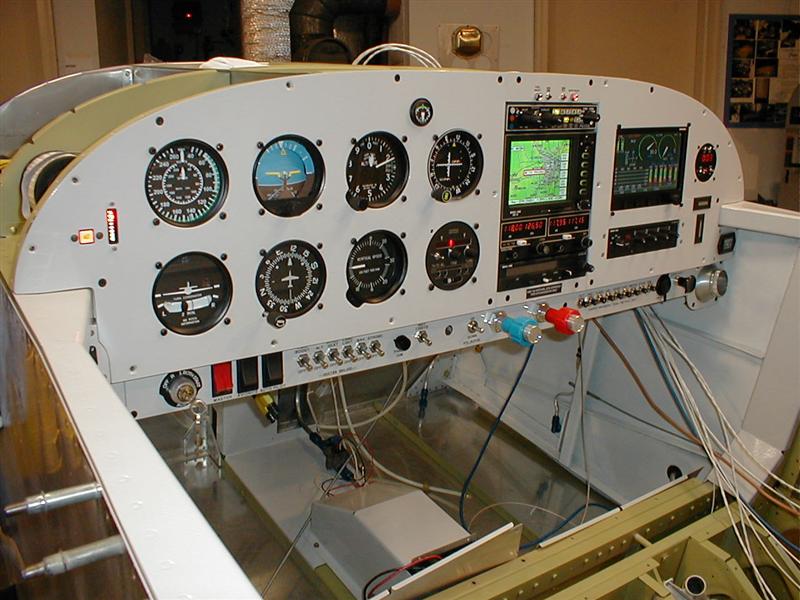
Look at all those little holes. I had screws, rivets and nuts holding it all together. The ELT and HOBBS cutouts needed to sit on top of some screws. Those screws had to be countersunk. WHAT? Well, as you get into it you'll notice that if you don't countersink the screws, you'll end up having to take more of it apart to remove the panel later on. I wanted the entire panel to be removable at any time. I didn't want it to take days and I didn't want to disturb surrounding wires, paint and all that other pretty stuff. I wanted a clean installation and removal process. If you look at the pictures about 20 below you'll see that I had to remove it for paint. Before that I had it all installed. Look at the before and after shots.

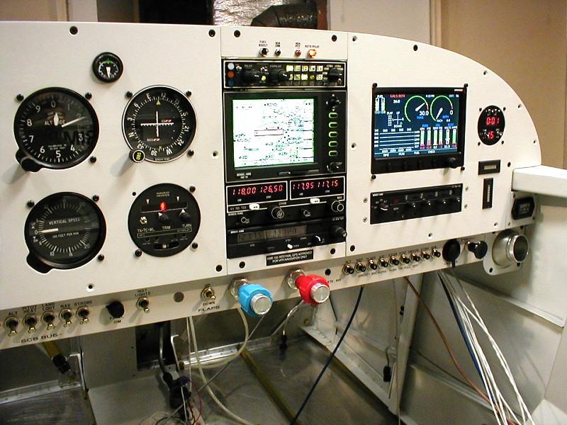
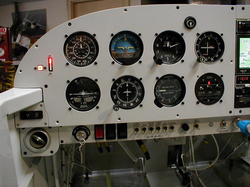
Man, I remember thinking about cutting all those instrument holes. It gives me the heebyjeebies just looking at that panel without cutouts. Don't worry, it's not that hard if you take your time. If you get anxious you may end up ruining the thing and hiring someone (Like Affordable Panels) to do it. That's fine too. I'd suggest that you make sure you have the correct hole saw(s). The center of your hole is critical for alignment with everything else. Take a look at the panel space. Think about what you have, what you would like to have, what you might forget and then save a few little spaces for extras.